Walnut Pedestal Table
A router jig makes easy work of shaping round and curved parts for this Regency-style pedestal table.
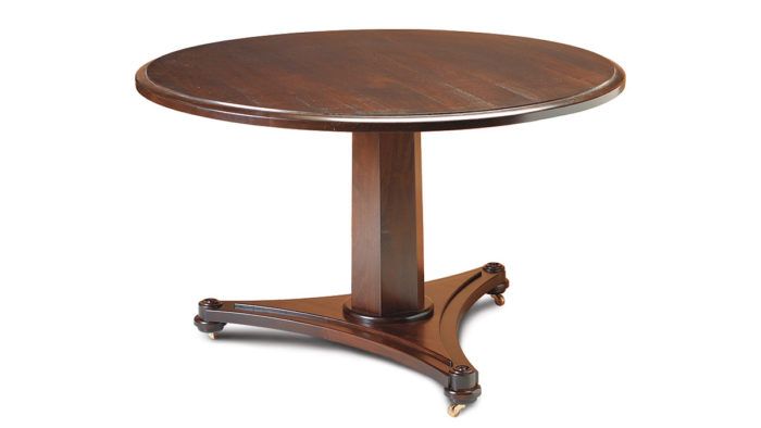
Synopsis: This reproduction of a 160-year-old French Regency pedestal table has many interesting details, not to mention a few challenges. Crafted of walnut, each piece is either curved or has a compound angle. Custom cabinet maker John Zeitoun designed a few jigs to make construction easier. He shaped the curved parts on the triangular base with a router attached to a trammel jig. A circle cutter on the drill press was used to shape a stack of disks into elegant feet, with no need for a lathe. And the six-sided tapered column, for which each segment has compound beveled edges, was cut on the tablesaw. A threaded steel rod feeds through each section of the table, holding it together.
I love flipping through books of antique furniture and looking over pieces at garage sales, and I jump at the challenge of reproducing an antique in my shop. Such was the case when a client showed me a picture of a 160-year-old French Regency pedestal table from the book The Furniture of Old Ontario (Macmillan, 1973) and asked if I could make it for him.
The picture didn’t explain construction techniques, but using generally accepted proportions, as well as considering the space it was to occupy, I was able to reproduce the table. According to the book, the original table had a hardwood base with bird’s-eye maple veneer and a pine tabletop. But I chose to make mine out of walnut.
Work From The Bottom Up
The table offers a few challenges. For one, each piece either is curved or has a compound angle. I was able to simplify the construction process by breaking it down into small steps and by using a few jigs.
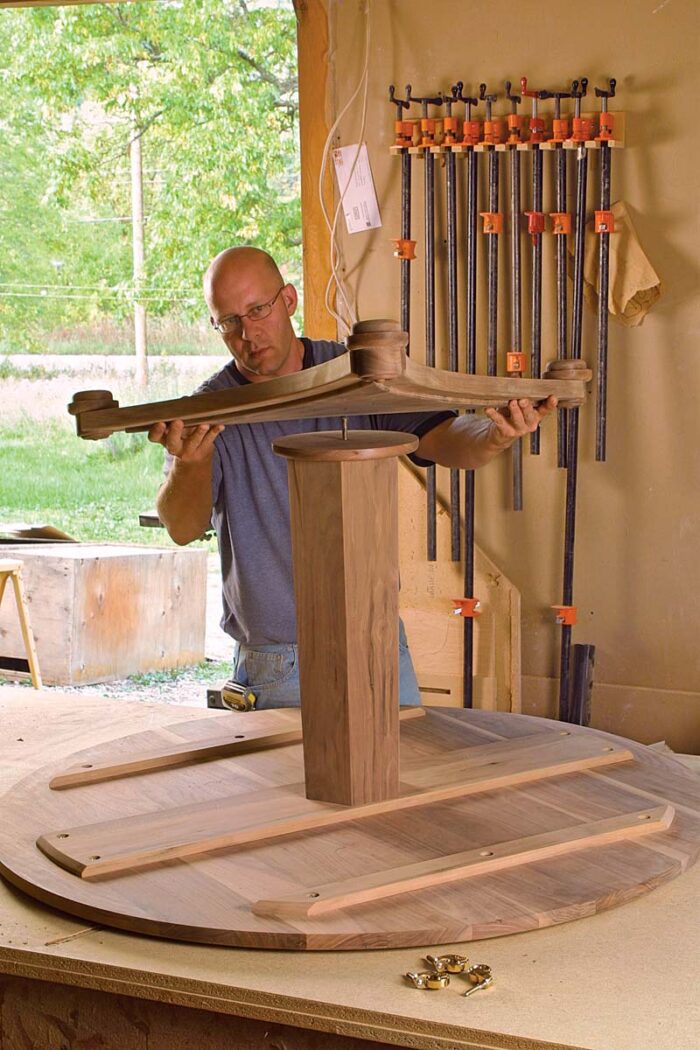 Prepare a trammel jig— The curved parts that make up the triangular base of the table are shaped using a router mounted to a large trammel device. The workpieces first are cut to rough size on the bandsaw and then are screwed to the base of the trammel jig, where a router is used to cut the inside and outside edges of each piece.
Before shaping the walnut, use the jig to make a particleboard template. You will use this template to roughcut the triangular frame parts on the bandsaw. Mount a 6 1/4-in.-wide by 34-in.- long piece of particleboard to the trammel jig with two screws driven into the underside of the jig’s base. Then position the router trammel on the jig, ensuring that the height of the pivot point is equal to the thickness of the workpiece being cut. Set the trammel to the distance of the inside radius and make several passes with the router, increasing the depth of the bit with each pass to prevent tearout and ease wear on the cutter and router. Reposition the router trammel to the distance of the outside radius and repeat this process.
Once the template is prepared, trace its shape onto the walnut and rough-cut three pieces on the bandsaw to within 1⁄16 in. of the line. Then attach each workpiece to the base of the trammel jig and follow the same procedure used to rout the template.
Cut flat surfaces on the three frame parts where they join—Use the tablesaw with a template and an auxiliary fence that acts as a template guide.
To make the template, lop off the top 10 in. of the trammel jig. This section, with its top corners cut at 30°, becomes your template. Attach the auxiliary fence to the tablesaw. Set the blade in line with the edge of the auxiliary fence and raise it until it just begins to cut into the fence above it.
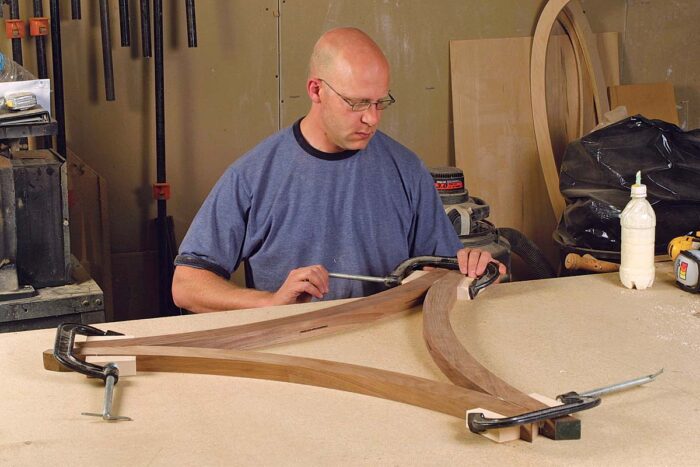 One at a time, screw the frame workpieces to the jig using the same screw holes from the routing process. Place the straight edge of the template against the auxiliary fence, and run it past the blade to remove any material that extends beyond the template.
On the resulting flat edges, use a biscuit joiner to cut slots into the inside edge, about 1 in. from the top edge. Locate the slots 21⁄2 in. from the corners, and also cut one at the center of each piece. These slots will house cleats that fasten the triangular center panel to the frame.
To assemble the base, simply glue and clamp together the frame pieces with the flat edges registered against each other and the screw holes facing down. Put the frame aside while the glue dries and get started on the triangular panel.
Shape the triangular panel—The curved triangular center panel is shaped similarly to the three frame parts. On the underside of a glued-up panel, lay out an equilateral triangle with sides that measure 301⁄2 in. Locate its center point, then mount the panel to another trammel jig good side down so that it pivots on its center. I drilled a 1⁄16-in. hole in the center of the panel as well as at the center point of the jig and aligned them with a 1⁄16-in. drill bit.
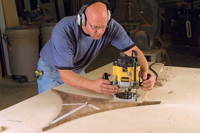 First, use a pencil in the trammel to mark the radius on each side of the triangular panel. To ensure that the triangle is properly aligned in the jig when marking the radius, double-check that the measurement from the trammel’s pivot point to each corner of the triangle is equidistant. Remove the panel from the jig and cut it out on the bandsaw to within 1⁄16 in. of the line.
Remount the panel on the trammel jig and set up the router to cut the radius on all three sides. Before routing, be sure that two corners of the triangle are equidistant from the trammel’s pivot point. Screw the panel to the base of the trammel jig to prevent the router from knocking it out of position. Rout the edge in several passes, exposing more of the bit with each pass. Unscrew the panel, rotate it to cut the next side, and continue the process until the radius is cut on all three edges.
The panel has a 3⁄8-in. rabbet to fit to the frame. Set up for this cut by extending the radius of the router trammel by 3⁄8 in. Again, screw the panel to the jig to prevent it from moving while you rout each edge. Last, turn over the panel and run a 1⁄4-in. roundover along each edge with a handheld router and a bearing-guided bit. Also, cut the three tips of the panel by hand to 161⁄2 in. from the center and round them over with sandpaper.
Assemble the base—The center panel is secured to the triangular frame using cleats housed in slots in the frame. Screw the cleats to the underside of the panel so they align with the slots on the inside edge of the frame.
Once the panel is attached to the base, drill out the ends of the base for the feet. Measure and mark the location of the feet 187⁄8 in. from the center point of the base. Drill the holes on the drill press with a 21⁄2-in. sawtooth cutter, centered on the mark. Lop off the excess material with a handsaw just past the centerline of the hole (191⁄8 in. from center). I marked this line with my pencil trammel, using the center of the base as the pivot point.
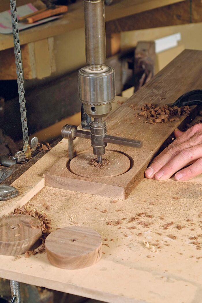
Build up the feet—If you own a lathe, constructing the feet is straightforward. But I don’t have a lathe, so I assembled the feet from individual pieces cut using a circle cutter on the drill press.
The circle cutter bores a 1⁄4-in.-dia. center hole in a workpiece while a spinning blade cuts the perimeter of the circle. The three circles in each foot require a roundover on one edge: 3⁄8 in. on the two lower circles and 3⁄16 in. on the top one. For safety, I secured the small workpieces to my bench by driving a screw through the 1⁄4-in. center hole so that the piece would stay put as I routed. The center hole also comes in handy for sanding: Fit a 1⁄4-in. bolt through the hole and then tighten a butterfly nut from the other side. Now you can chuck the bolt in the drill press and sand the workpiece as it spins.
The feet are topped with rosettes cut on the drill press using a rosette cutter. Once the circles and rosettes have been prepared, glue the parts into stacks. Align the three circles with a 1⁄4-in. dowel fitted through the center holes. To prevent the rosette from creeping when clamping pressure is applied, drill a few clearance holes in the top of the foot, cut off the heads of 3⁄4-in. finishing nails, and insert the nails upside down into the holes so that the points stick out by 1⁄16 in. Center the rosette on the foot and apply pressure.
After the feet are assembled, apply glue only to the adjoining surfaces on the feet and base, and clamp the feet in place. The brass casters are installed after a finish has been applied.
Prepare The Column Staves
 Constructing the hexagonal tapered column is another challenging part of this project. Each of the six staves tapers toward the top, and all four edges of each stave are beveled. The top and bottom edges of each piece are crosscut at 11⁄2° parallel to each other so that they join flush to the base and tabletop. The side edges are beveled at 30°.
Start with six pieces of material, each measuring 3⁄4 in. thick by 5 in. wide by 23 in. long. Cut a 11⁄2° bevel on the ends, parallel to each other, so that the finished length of the stave is 225⁄8 in. (measured from toe to heel on the face). Next, make and fasten a template (see p. 66) to the inside face of each stave, one at a time, and trim the workpieces on the tablesaw with the template guide attached to the saw fence.
Finally, cut the staves to width with the blade tilted to 30° (the 11⁄2° taper changes this bevel angle, in theory, but not enough to matter in a practical sense). Set the fence to remove 1⁄2 in. of material, measured from the edge on the outside face. Once you are happy with your setup, run each workpiece across the tablesaw with each edge registered against the fence. My tablesaw has a right-tilting blade, so the bevels are cut with the screw-hole side of each stave facing the table.
Assemble the column—The column should go together easily. Place the pieces edge by edge with the outside face up and run several strips of tape across them to keep them aligned. Turn over the pieces, apply glue to the joining edges, and roll up the whole column.
Finally, apply clamping pressure to the column with strap clamps. Insert cauls between the column and the straps to spread the clamping pressure.
At the bottom of the column is a 3⁄4-in.-thick by 91⁄2-in.-dia. disk. Use the router trammel to cut this piece, then round it over with a 3⁄8-in. bearing-guided bit.
Keep The Tabletop Flat
To make the 48-in.-dia. tabletop, I glued up 5-in.-wide boards into a panel. I alternated the direction of the growth rings and paid close attention to the grain to prevent warping or twisting.
I cut the panel round with the router trammel pivoting in a hole drilled into the underside of the table at the center. On the round top, I cut the edge profile with a bearing-guided router bit, creating a profile similar to the table in the photo. If you’re not interested in buying what is likely to be a one-time-use router bit, you can use any profile you choose.
The original table did not appear to have an apron around the underside of the top. However, a top at those dimensions could not have withstood much weight across its grain without additional support. My solution was to attach long cleats, running across the grain, to the underside of the table. To allow for wood movement, the cleats are screwed in three locations (three on each side for the center cleat) and fitted into oversize screw holes with washers.
Assemble With A Center Rod
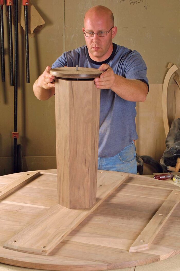 With the exception of the top, all of the table parts are sandwiched together using a 3⁄8–in.-dia. threaded rod with a washer and nut at both ends. The nut at the top of the rod is set into a 3⁄8-in.-deep square-bottom clearance hole in the center cleat. Countersink 3⁄8 in. into the tabletop, as well, to accommodate the remainder of the nut and washer. Use Loctite Thread Lock to keep the top nut from spinning when tightening the other end; however, before you assemble the table, finish all of the parts and install the brass casters.
Lay the top upside down on the workbench with the threaded rod extending up out of the tabletop, and drop the column and base over the threaded rod. Center all of the parts and tighten the nut on the bottom end of the threaded rod. Finally, flip it over, stand back, and take a well-deserved look.
From Fine Woodworking #176
For the full article, download the PDF below:


Log in or create an account to post a comment.
Sign up Log in